
TM 11-7025-221-20
2-5. Rear Connector Signal-To-Pin Relationships - Continued.
J11 Signal-To-Pin Relationship - Continued
J11 Signal-To-Pin Relationship
Signal
Pin
I/O
Signal
Pin
I/o
--
--
Not used
J,K
A
Receive data from TD-660 group 3
I
l
Receive data from TD-660 group 4
L
Receive data group 3 shield
I
B
--.
I
Receive data group 4 shield
M
Not used
C,D
N
Unbalanced data group 3
0
E
0
Unbalanced timing group 3
P
0
Unbalanced data group 3 shield
F
0
Unbalanced timing group 3 shield
R
0
Unbalanced data group 4
0
Unbalanced timing group 4
G
0
Unbalanced data group 4 shield
s
H
0
Unbalanced timing group 4 shield
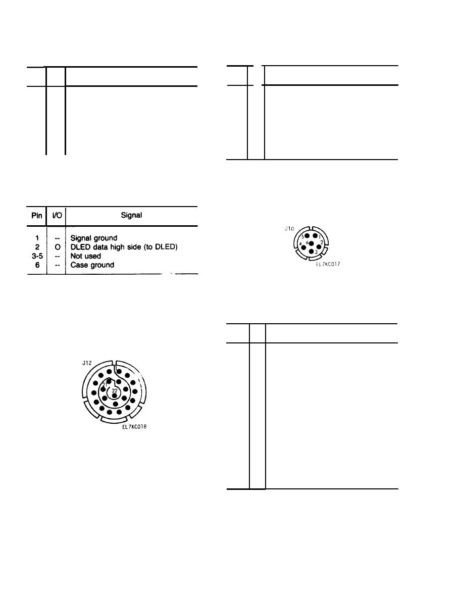
i. Connector J10 (V3 and V4 models only). Signals to the DLED (in red form) are routed through
this connector.
J10 Signal-To-Pin Relationship
j. Connector J12. This connector is used for input/output signals for the Vinson, input/output signals
for the dedicated user, and TD-1337(V)/G remote alarm signals.
J12 Signal-To-Pin Relationship
Signal
Pin
I/O
--
1
Ground
Vinson data in (from Vinson)
2
I
Vinson data out (to Vinson)
3
0
4
I
Vinson press-to-talk
--
Not used
5
Loop modem receive data low side
6
I
Loop modem receive data high side
7
I
8
0
Loop modem transmit data low side
Loop modem transmit data high side
9
0
10
--
Not used
11
--
Ground
Receive alarm
12
0
13
0
Transmit alarm
14
--
Ground
Not used
15-22
--
2-6. Unpacking.
There are no special or unique unpacking requirements for the TD-1337(V)/G. No loose or separate parts
or cables are shipped with a TD-1337(V)/G.
2-8
