
TM 11-5820-880-12
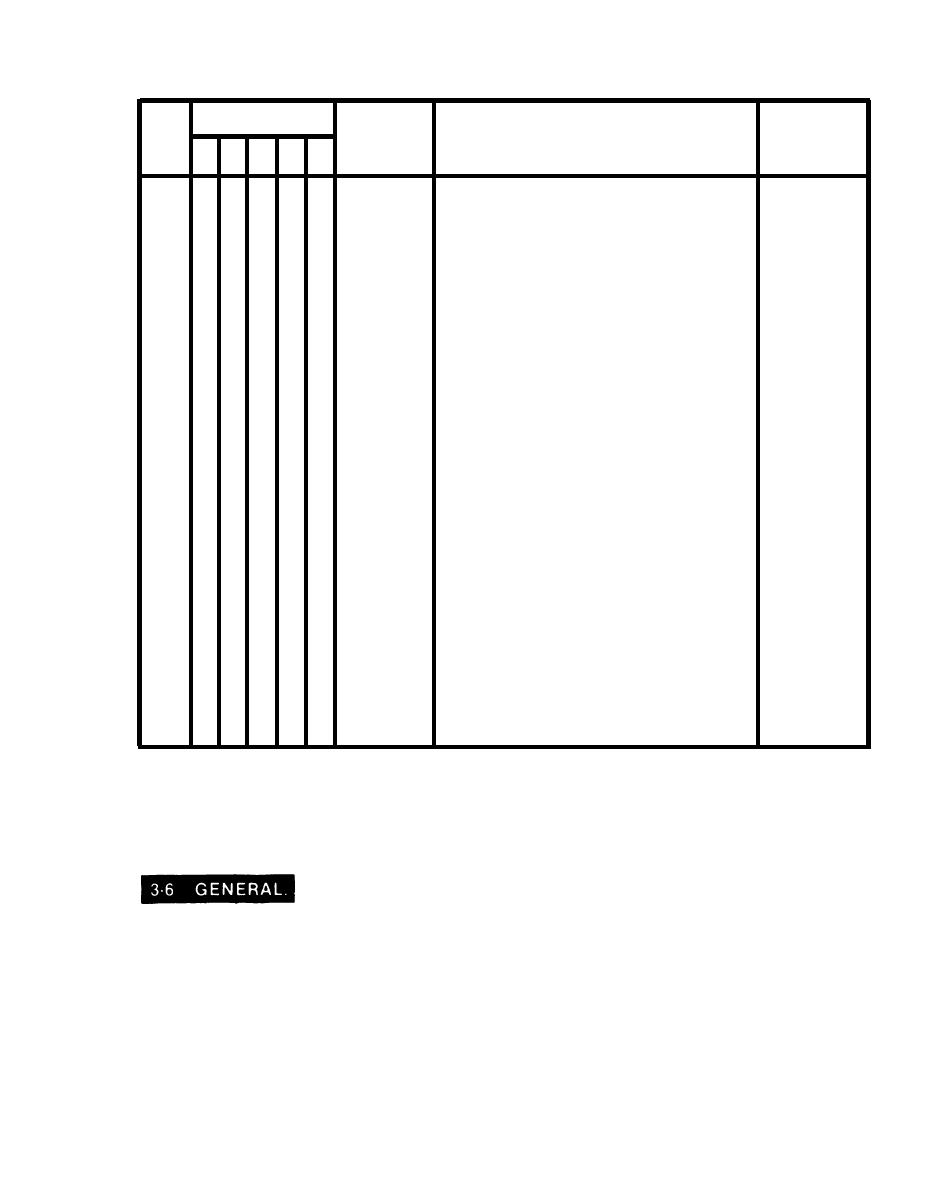
Table 3-1. Operator Preventive Maintenance Checks and Services (Continued)
Interval
Procedures
Equipment is
Item
Item to be
check and have repaired
not ready/
Inspected
No.
or adjusted as necessary
available if:
B
D
A
W
M
*
18
*
Check upper rear rf coax connector on
Damaged or
the band-pass filter for dents or damage.
dented rf coax
connector.
*
19
*
Check antenna rf connector on side of
Rf connector
coupler for damage.
damaged.
*
20
Check to see that all connectors are in
*
good condition and tightly connected to
proper receptacles.
*
21
*
Wipe off any grease, oil, moisture, or other
foreign matter from cables and
connectors.
Multiplexer
With the transceiver turned on and set to
22
*
*
*
*
operation
the tune frequency of the band-pass filter
through which it is to transmit, and with
all the other band-pass filters tuned to
their assigned frequencies, key the
transceiver and talk to a distant station.
23
Observe the meter for correct deflection
*
*
*
when the transceiver is keyed.
Check the output from the transceiver by
placing the meter function switch in the
60W-F position.
Observe the meter for 60 watts.
SECTION IV
TROUBLESHOOTING
The troubleshooting table lists the common malfunctions that you may find during the operation
or maintenance of the 2-channel or 5-channel multiplexer. You should perform the test,
inspections, and corrective actions in the order listed.
This manual cannot list all malfunctions that may occur, nor all tests or inspections and
corrective actions. If a malfunction is not listed or is not corrected by listed corrective actions,
notify your supervisor.
3-5

