
TM 11-5820-880-12
The central resonator is composed of inductor L9 and variable capacitor C13. The variable
capacitor is mechanically linked to the center tuning knob on the front panel. The tuning knob is
used for selecting operating frequency and for coarse and rf tuning adjustment. The resonator
also supplies a voltage sample to the 90 phasing discriminator.
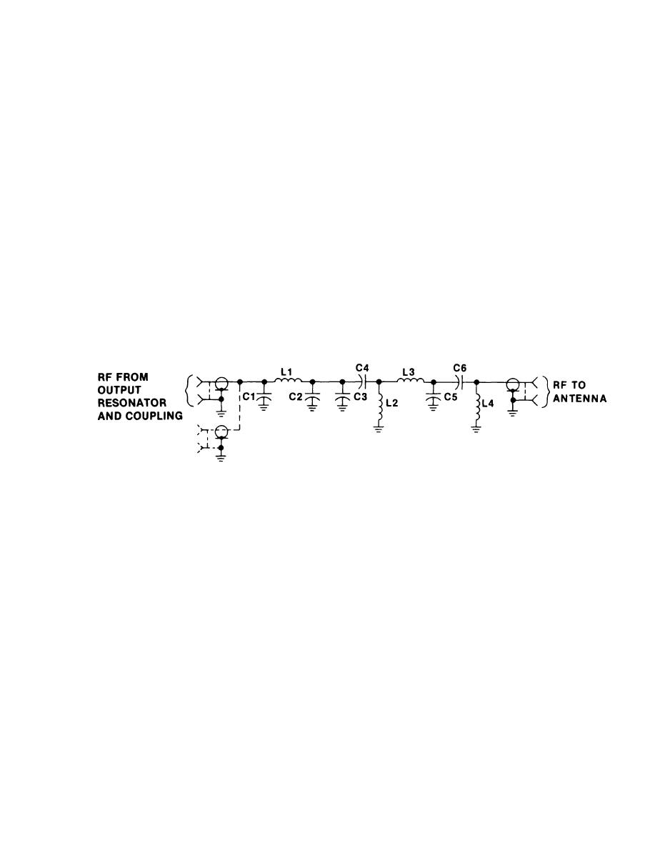
The output resonator and coupling is composed of variable capacitor C14 and tapped inductor
L10. The variable capacitor is mechanically linked to the lower tuning knob on the front panel.
The tuning knob is used for selecting operating frequency and for coarse and rf tuning
adjustments. Tapped coupling of inductor L10 provides a 7-ohm resistive load to the coupling
network.
c. Coupling Network. The coupling network translates the 7-ohm resistive load of the output
canceling network to optimize the VSWR across the operating frequency range. The divider
network configuration determines the resistance transformation and the values of the
components determine the optimization of the VSMR. Capacitor C1 is a compensating capacitor
that has a value determined by the number of channels comprising the multiplexer.
1-13
