
TM 11-7025-221-20
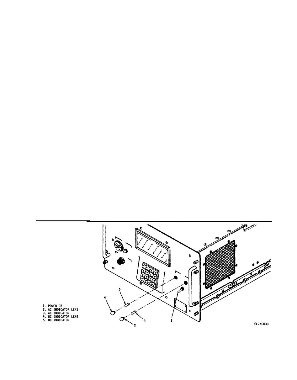
2-19. POWER AC and DC Indicator Replacement Instructions.
This task covers:
b. Installation
a. Removal
INITIAL SETUP
Equipment Condition
Applicable Configurations
Notify local users and remote TD-1337(V)/G(s)
that your TD-1337(V)/G is being turned off
All models
for maintenance.
Tools
General Safety Instructions
None
None.
Personnel Required: 1
Tactical Satellite Microwave System Operator
MOS 26Q
Remarks
Action
Location/Item
Removal
Set to OFF
1. POWER CB (1 )
Turn counterclockwise to remove.
Remove
2. Lens (2 or 4) for
indicator being
replaced
Pull it straight out of housing.
Remove
3. Indicator (3 or 5)
being replaced
Installation
Press it straight into housing.
4. Indicator (3 or 5)
Install
Turn clockwise to install.
Install
S. Lens (2 or 4)
If indicators do not light, refer
Set to ON. Cheek that POWER AC
6. POWER CB (1 )
to troubleshooting procedures (para 2-9).
and DC indicators are Iit.
2-39

